Abb Ach550 Control Wiring Diagram
Https Www Galco Com Techdoc Abbi Ach550 Vcr 023a 4 F267 Pub Pdf

Yz 3618 Abb Ach550 Wiring Diagram

Schematic Wiring Diagram Ach 088 Diagram Base Website Ach 088 Multiplevenndiagram Istitutocomprensivolagonegro It

Zz 5749 Vfd Bypass Wiring Diagram Free Diagram
.PNG)
Abb Ach550 Series Ac Drives For Pumps Buy From Official Distributor

Abb Ach550 Manual English

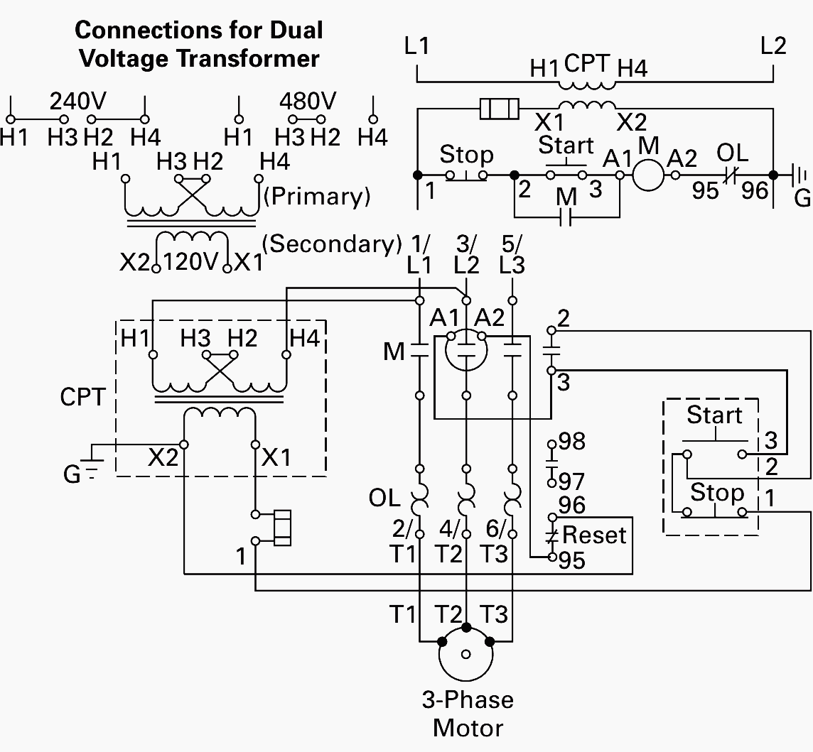
Abb ach550 wiring diagram building circuitry representations show the approximate places and also interconnections of receptacles illumination and also irreversible electrical services in a structure.
Abb ach550 control wiring diagram.
Http Admeng Ca Files Ach550 Product Bulletin Pdf

Abb Vfd Wiring Diagram Free Picture Schematic

Ty 6266 Abb Ach550 Wiring Diagram Schematic Wiring

Ach550 Bcr Bdr Vcr Vdr E Clipse Bypass Drives User S Manual Ach550 E Clipse Bypass User S Manual Pdf Free Download

Abb Vfd Motor Starter Wiring Diagrams Abb Ach550 Wiring Diagram Free Wiring Diagram Vfd Wiring Diagram A Machmotion Abb Acs550 Ac Drive Basic Startup Youtube Manual Motor Starter Motor Protection And Control

Hk 5747 Abb Ach 501 Wiring Diagram Free Diagram
Abb Drive Ach550 Control Wiring Abb Ach550 Wiring Diagram Sample Wiring Diagram Sample Abb Ach550 Wiring Diagram Free Wiring Diagram Abb Ach550 Wiring Diagram Download Wiring Collection Abb Vfd Wiring Diagram Collection

Diagram Based Abb Ach550 Wiring Diagram Completed Diagram Base Wiring Diagram Philippe Cadene Jablonskidiagram Portplaisancecalvi Fr
.png)
230v Micro Vfd
1dcf Abb Vfd Control Wiring Diagram Wiring Library
Abb Ach550 Wiring Diagram Abb Ach550 Wiring Diagram Sample Wiring Diagram Sample Abb Wiring Diagram Wiring Diagram Database Abb Ach550 Wiring Diagram Download Wiring Collection Abb Motor Drawings Abb Vfd Wiring Diagram

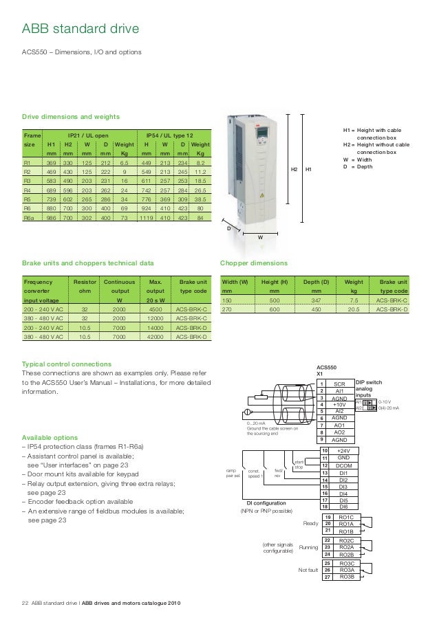
Abb Ach550 Ac Hvac Drive Specifications

Gf 5864 Mcc Panel Wiring Diagram Pdf Along With Abb Vfd Control Wiring Diagram Free Diagram
Eaton 3 Pole Contactor Wiring Diagram Diagram Base Website Wiring Diagram Venndiagramgoogle Habitants Bergeyre Fr

Lo 4130 Likewise Abb Vfd Control Wiring Diagram Moreover Wiring Single Phase Download Diagram

Lt 4807 Acb Wiring Download Diagram
Abb Ach550 Full Version Enervex

Practical Machinist Largest Manufacturing Technology Forum On The Web
Https Encrypted Tbn0 Gstatic Com Images Q Tbn 3aand9gcqkpwgxtb35xi46wo7jqo Njpu4xfaqfng1l 9y 52mt6xwrt0f Usqp Cau

Wiring Diagram Of Detroit Diesel 60 Series With Oil Temperature And Engine Brake Or Turbo Compressor Wiring Diagram Detroit Diesel Detroit Diesel
Hvac Talk Heating Air Refrigeration Discussion
Https Library E Abb Com Public D17fe8cfbd28404eab3fe385df4a6b6c 3axd50000264469 Revb Pdf

Index Of Docs Abb Drives Drawings Ach550 Pdr 06a9 4 B058
Http Www Mdm Construction Com Wp Content Uploads Submittal For Condensor Motor Vfd Pdf
Source : pinterest.com
